Phantom
|
|
Phantom is my first 3 kg Sumo Robot. This category of sumo has to fit inside
a 20cm square and weigh under 3kg. For an illustrated description of the
competition and rule, check out the
Sumo Rules
page by David Cook. A more formalized treatment of the rules may be found
on the
Northwest Robot Sumo Tournament site.
It started out as the
Viper kit from
LynxMotion. I noticed that they changed the Viper kit slightly
just after I purchased it. The new kit appears to make it easier to change
batteries.
|
|
|
|
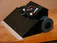
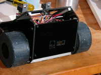
Side View
This is the overall view of Phantom. It's pretty much the stock Viper kit,
except that I machined up a nice wedge for the front. The 4 screw holes
across the front secure the top to the scoop. The screws were not
present in the picture. The wheels have a thin coating of RTV Silicon
on them for improved traction. Phantom made its debut appearance at the
International Robot Sumo Tournament in Seatte in March, 2004. Unfortunately
the motors I selected didn't have enough torque - Sigh.
Bigger...
|
|
|
|
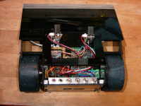
Top View
Here's the top view. The red bush button is a reset switch. The black
pushbutton is the start button. The leftmost toggle is for the motor
power, and the one next to it is the CPU power. The third toggle is a
run/start switch, and the rightmost toggle is a hint to determine if
Phantom should turn left or right when starting.
When the run/start switch is in the start position, then the startup
code pauses and waits for the black push button to be pressed before
starting the 5 second countdown. If the run/start switch is in the run
position, then the startup code doesn't pause. This allows the robot to
not pause for 5 seconds if it gets reset accidentally.
Bigger...
|
|
|
|
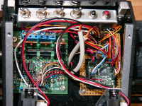
Electronics
Here's a closeup of the electronics. I'm using the
"Maxi Dual 10A H-Bridge"
from the "Robot Store" (which doesn't seem to exist anymore), and
the MegaBitty purchased from the
"Mark III Robot Store".
The MegaBitty includes a couple of H-Bridge chips, but they're only rated
for 500 ma, so I didn't install them and just soldered wires from the
appropriate pads.
The arrangement of the connectors on the MegaBitty wasn't convenient for
all of the sensors that I had, so I created a little breakout area on
a Radio Shack perfoard to rearrange the connectors the way I wanted them.
The MegaBitty has a 9v battery dedicated to it, and the motors have 10
NiMH AA cells.
Bigger...
|
|
|
|
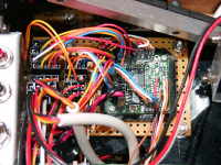
MegaBitty
Here's a closeup of the MegaBitty, which gives more than enough CPU power
for this sumo in a 0.9" square package. The connectors on the MegaBitty
board have a 0.05" spacing, where the connectors on my breakout area and
the perfboard are 0.1". Those are 0-80 screws in the corners.
Bigger...
|
|
|
|
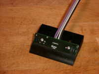
Phantom Rear
Here's the rear view, where the serial port (using a standard telephone
jack) and the ISP (In System Programming) port are visible. The reason
that the hole around the telephone connector is too big is because I
originally used the handset connector instead of the normal line connector.
Whoops.
Bigger...
|
|
|
|
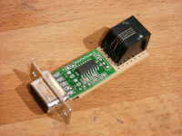
Serial Adapter
The MegaBitty only has TTL level RS-232 on it, so some type of level
shifting is required.
"HVWTech" made a very nice little adapter.
Once feature that I really like about the HVWTech adapter is that by soldering
some 0.1" headers in the 4 pins along the back and the two pins next
to the "HVWTech" on the board, and the two pins in the same spot across
the board, you can then plug it into a solderless breadboard.
Bigger...
|
|
|
|
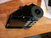
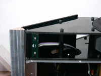
Scoop Modification
In order to fit on the aluminum scoop, I had to cut 3/4" off the stock scoop
as well as cutting the tips off the vertical members. In this picture you
can also see the mounting spots for the rare earth magnets. It turns out
that with the motors I have and the softness of the wheels, I couldn't
use the magnets.
Bigger...
|
|
|
|
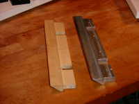
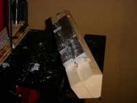
Scoop and Prototype
Here's a picture of the scoop prototype that I made out of MDF, alongside
the finished scoop made from aluminum. The angle of the tip is 35 degrees.
Bigger...
|
|
|
|
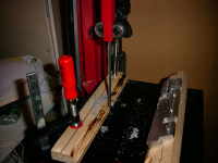
Jig
Here you can see the Jig I used to cut the rough 35 degree angle using
the bandsaw, as well as the finishing cuts on the mill. It's made from
two 3/4" pieces of MDF which have been glued together.
Bigger...
|
|
|
|
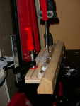
Fence
I used a piece of plywood for my fence to do the rough cut on my metal
bandsaw.
Bigger...
|
|
|
|
Rough Cut
Here you can see the rough cut being done. By the time I was finished, the
aluminum was too hot to touch.
Bigger...
|
|
|
|
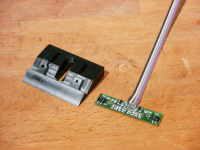
Line Sensor and Mount
Here's the
line sensor
that I'm using (one on each side - also from the Mark III Store). It was intended
to be used as a micro-sumo line sensor, but I used one on each side. I just
had to file down the sides a wee bit to get it to fit. The mount was machined
from Delrin. I was originally going to put two slots for mounting, but
realized that I only needed one in the center. This allows the distance from
the sensor to the ring to be adjusted.
Bigger...
|
|
|
|
|
|
|
|
Home
- Line Maze 2006
|