Installing the Sherline Threading Attachment
|
|
I installed the "permanent" portion of the threading attachment and ran
into a little bit of difficulty. I thought I would document what I did,
since I found the
Sherline instructions
to be not as clear as they could be.
You can click on the thumbnail to get a larger version of the picture,
and you can click on the larger version to get the full size image.
|
|
|
|
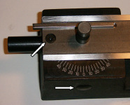
Headstock Removed
Here's a picture with the headstock removed. You'll want to completely
remove the indicated screw and pop off the plastic cover on the front.
Bigger...
|
|
|
|
|
|
|
Leadscrew Support
This is what the leadscrew support looks like once it's been removed. It's
oriented here with the curved opening facing down, which is how it faces
when it's installed.
Bigger...
|
|
|
|
Fixed and Sliding Shafts
Here we can see the fixed shaft on the left and the sliding shaft on the
right, in the orientation that they'll go into the leadscrew support, which
you can just see on the right of the picture.
Bigger...
|
|
|
|
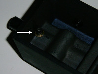
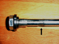
Burrs
After inserting the fixed and sliding shafts into the leadscrew support they
should rotate with no binding. Be careful - The pin coming out of the end
of the fixed shaft (which is the natural thing to grab onto) can have sharp
edges. Mine had some binding. I took some 600 grit sandpaper, wrapped it
around the fixed shaft and twisted the fixed shaft back and forth a few
times. Burrs (indicated by the arrow) immediately became obvious. I filed
these down, and the binding disappeared. I didn't have any problems with the
sliding shaft, but you should check yours.
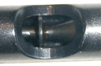
The screws from the top and bottom fit in the big square groove. This allows
the fixed shaft to rotate freely, but not to slide in and out of the
leadscrew support.
Bigger...
|
|
|
|
|
|
|
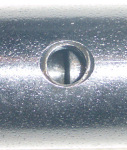
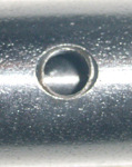
Too Far Left
Looking through one of the screw holes in the leadscrew support, check to
see if the groove in the fixed shaft is lined up with the screw hole. Here,
the fixed shaft is too far to the left.
Bigger...
|
|
|
|
|
|
|
|
|
|
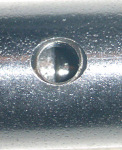
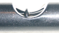
Sliding Shaft Position
This is about where the sliding shaft should be when the fixed shaft is in
the correct position.
Carefully insert the leadscrew support back into the lathe base, with the
curved portion pointing down. Put the screws back in. The engagement lever
should slide in throught the hole in the front of the base and engage with
"bump" on the sliding shaft.
Bigger...
|
|
|
|
|
|
|
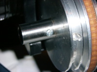
Mangled Drawbolt
After installing the "permanent" portion of the threading attachment, I had
some troubles tightening and loosening the drawbolt in the headstock.
I removed the drawbolt to discover this.
Bigger...
|
|
|
|
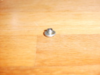
Guilty Party
Here's the guilty party (well, all right it was really my fault for not
stopping sooner when I encountered resistance).
Bigger...
|
|
|
|
Trimmed
I trimmed the length of the screw by half, so that none of the screw actually
projected into the hollow portion of the spindle.
Bigger...
|
|
|
More pictures to come later...
|
|
Home
- Machinist
- Modifications/Improvements
|