CNC Threading
| One of the really cools things that you can do with a CNC lathe is to do threading. |
|
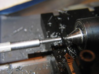
First PartThis is my first threaded part using the CNC threading capability from Turbo-CNC. This piece is cut from a 1/4" steel rod (CRS - not leaded). The thread is 4mm x 0.7mm (cut using my imperial lathe - which doesn't really matter with CNC). I created the G-Code for the basic outline using CAD2Lathe and added the threading passes by hand. The gouge out of my live center was caused by me crashing the lathe :( I entered the position of the toolbit using the diameter rather than the radius and the computer happily tried to drive the toolbit somewhere on the other side of the live center - whoops. It also chipped the end of the carbide toolbit. Good thing I had a spare. I'm thinking that I should setup Turbo-CNC to use diameter mode. Firstly, when you measure anything on the lathe you always measure the diameter. Secondly if you screw up and enter the radius as the position, the worst thing that happens is that you don't cut anything at all rather than crashing. Bigger... |
 |
Movie of CNC threadingThis is a rather large clip (22Mb and 9:04 in length) which shows the part pictured above being made completely from scratch. Since this was my first part, I didn't do everything right. I was using constant depth of cut rather than constant volume of cut, and I didn't do any spring passes. |
 |
Small version of CNC threading movieThis is a much smaller clip (only 3.2 Mb and 1:13 long) which shows the last pass of the thread being cut, followed by the test fit of the nut. |
|
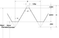
Thread profileHere's your basic thread profile, taken from Machinery's Handbook , 20th edition, page 1275. Using basic trigonometry, tan( 30 ) = (p/2) / H, so H = p/( 2 * tan( 30 )), or H = 0.866 p Since the typical tool is a sharp pointed V, the threads we create will extend all the way to the points (at the bottom). Bigger... |
|
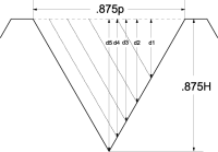
Depth of CutIMService makes available a Freeware Threading Program which calculates thread depth. Intrigued, I decided to figure out the math behind this. For reference, here are same basic formulas for calculating The Area of Some Simple Polygons. Basically, the area removed on each pass is equal. The area of a triangle is base times width divided by 2. So the total area = (0.875p x 0.875H) / 2 = (0.875p x 0.875 x 0.866p) / 2 = 0.3315 x p x p (or 0.3315 x p squared) Using the formula from the previous step (which preserves the angle) we get total area = (0.875p x 0.875 x p/( 2 * tan( 30 ))) / 2 = 49 x p x p / ( 64 * 4 * tan( 30 )) = (49 x p x p) / (256 * tan(30)). I converted the 0.875 back into 7/8 to give integer numbers. For a given depth d, d = base / (2 x tan(30)), so base = 2 x d x tan( 30 ), and the area = (base x depth) / 2 = (2 x d x tan(30)) x d / 2 = d x d x tan(30), so we can calculate d = sqrt( area / tan(30)) In this example, we're doing 5 passes, each with an equal area. So d1 = sqrt( 1/5 of total area / tan(30)). d2 = sqrt( 2/5 of total area / tan(30)), and so on. The thread22 program allows a Ratio value to be specified to allow the last pass to be some percentage of the other passes. If we wanted 5 passes with Ratio set to 0.4, then the formula for the area of pass 1 would be 1/4.4, and the area for the 2nd pass would 2/4.4 an so on. Generalizing for pass i would give (i / ((num_passes - 1) + ratio) x total_area) except for the last pass which would use the total_area. Bigger... |
|
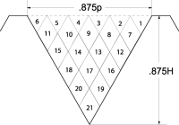
Depth of Cut, an alternativeFor small lathes, and larger threads, the above technique doesn't work very well. For example, on my Sherline lathe, if my Z axis moves at 20 IPM, and I'm trying to do a 3/8-16 thread, then I have to reduce the RPM down to 320 or below. With a pulley drive, this would be fine, but with the variable speed motor, you loose torque going that slow, so using the technique above tends to stall as the cuts get wider (even though its removing less material). Having it nibble away smaller fixed amounts each time (like this picture shows), seems more appropriate. Bigger... |
|
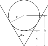
Allowing for a radiused toolbitHere's the math behind compensating for the radius on the end of the toolbit, r represents the radius of the toolbit. Given r and the angle (30 degrees) we know that sin(30) = r / h. So h = r / sin( 30 ). What we really want is c, which is amount that we need to compensate for when using a radiused toolbit versus a sharp pointed toolbit. c = h - r = r / sin(30) - r = r / 0.5 - r = 2r - r = r. That was a lot of work to come up with a simple answer. Bigger... |
Home - Machinist - CNC